Source Creation Tutorial
This tutorial describes the procedures used to locally control the clustering within a geometry using sources.
CENTAUR has two basic types of sources: CAD sources and Geometric Sources. CAD sources are sources attached to parts of the CAD including Curves, Panels and Groups. Geometric sources are sources that are described by various geometric shapes including Cylinders, Boxes, etc. This tutorial describes the generation of both types of sources.
Sources will be created at each of the three stages of mesh generation: surface, prism/hex and tetrahedra. Using this method allows for the grid to be optimized for the specific needs of an application in a straightforward manner.
- Create Surface Sources (CAD and Geometric)
- Create a Prismatic Source
- Create a Tetrahedral Source
Table of Contents
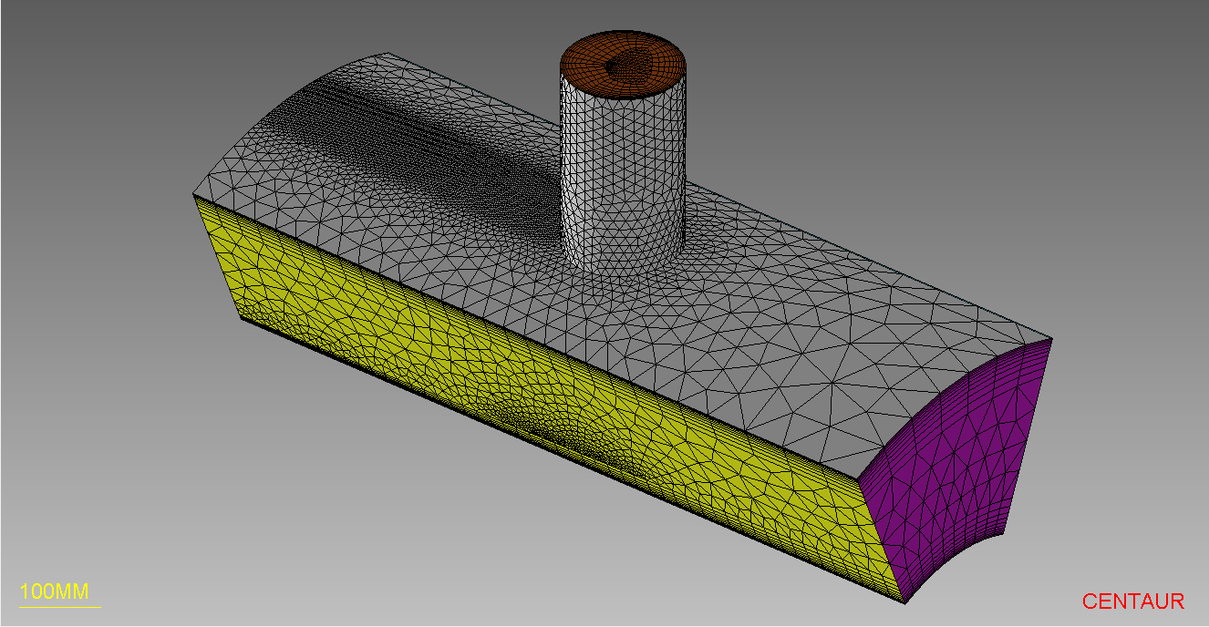
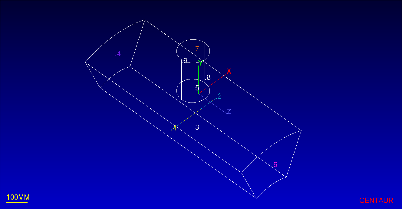
The geometry used for this tutorial is a periodic annular tube geometry that has a smaller cylindrical inlet tube connected to the main passageway. The restart file contains both the geometry and the setup from the Basic Mesh tutorial.
The tutorial file can be found in the “CENTAUR_Tutorials” folder located in CENTAUR’s installation directory, or you can download it using the following link:
Step 1: Load the Geometry
The first step is to start the CENTAUR Graphical Interface and load in the tubes.rst file via the File>Open… option.
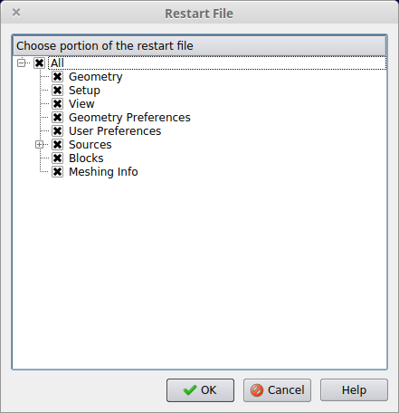
When loading the .rst file, there will be a prompt asking which modules should be loaded. Make sure to select All modules or All modules except User Preferences.
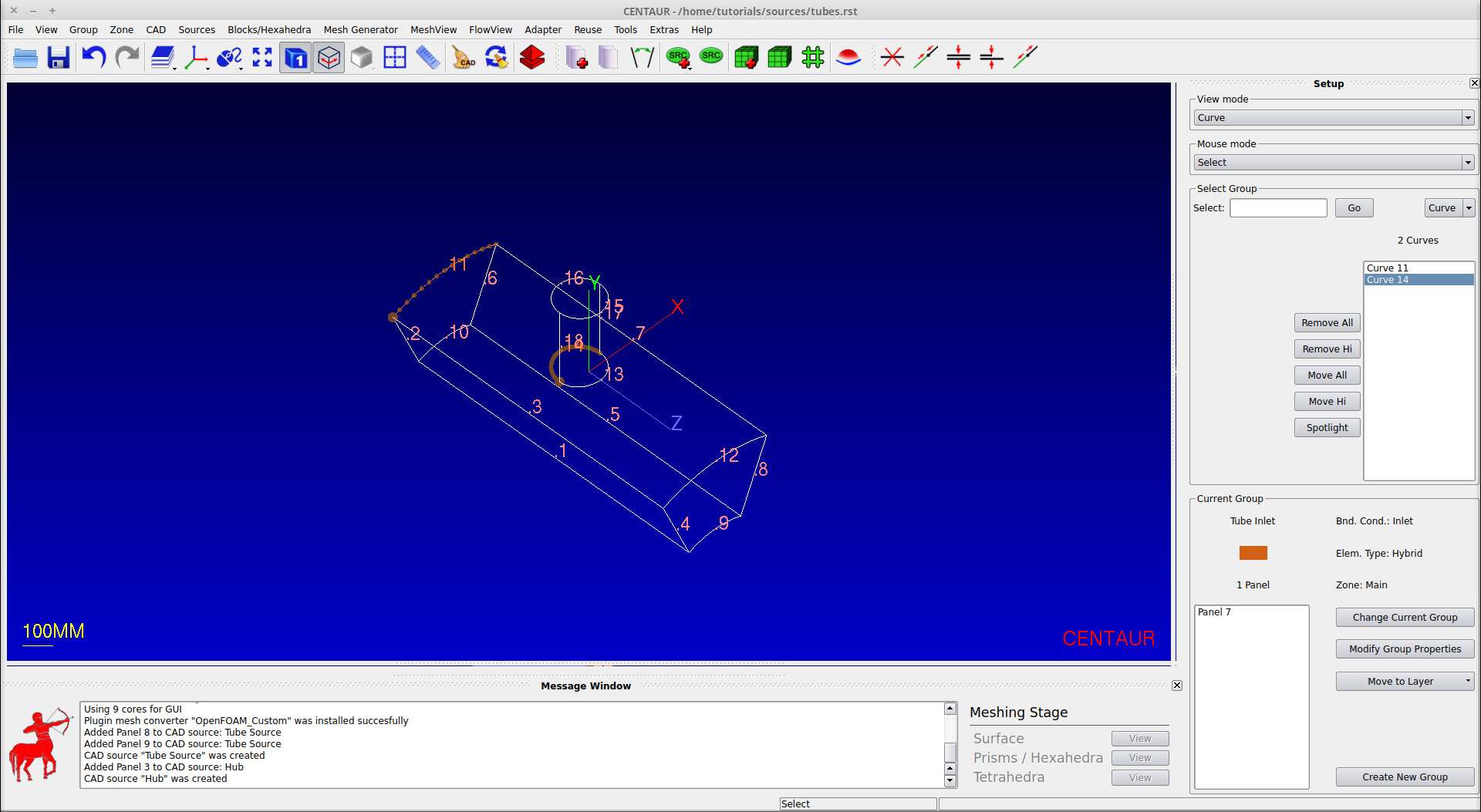
This will open the main window with the tubes geometry already loaded including the setup from the Basic Mesh tutorial:
Step 2: Create Surface Sources
The surface clustering can be locally modified using surface sources. The following sources will be created: a CAD source that will increase the clustering on panels 8 & 9, a second CAD source that will increase clustering on panel 3, and a cylindrical source that will increase clustering on the upper surface. These sources are created as follows:
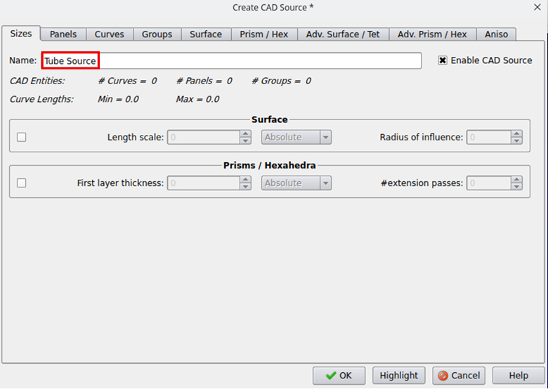
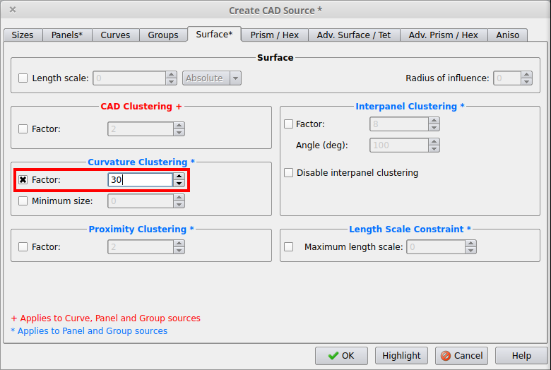
Source 1 (CAD Source):

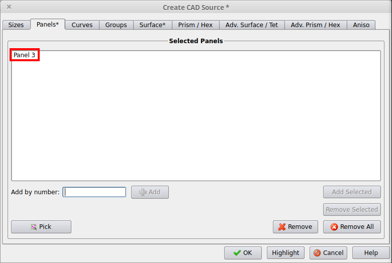
Source 2 (CAD Source):
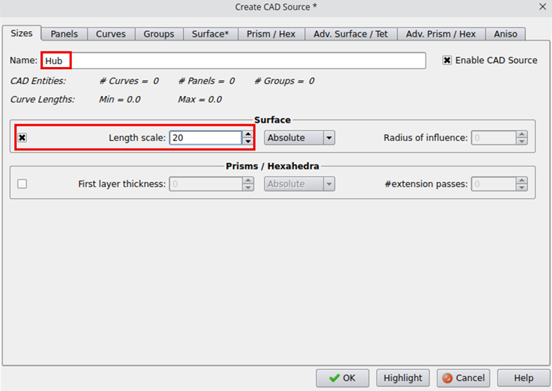
Naming the 2nd CAD source and setting the surface size parameter.
Source 3 (Geometric Source):
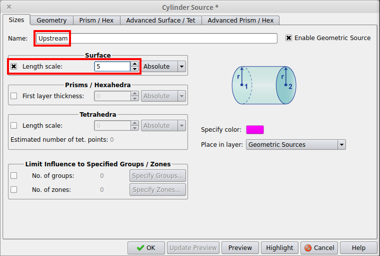
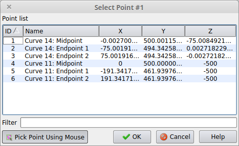
The location of these curves including the midpoints that will be used to create the source can be stored by adding the sources to the Point List using the L hotkey twice (once for each curve) or use the Tools>Point List>Add Points of Highlighted Entities option.Next use the Source>Create Source>Geometric Source>Cylinder… option to create a cylindrical source. In this source dialog box, give it a name, Upstream, activate it for the surface and give it a value of 5. Then switch to the Geometry tab, set the Radius to 50, and set the location of the source using the Choose Point buttons to select the midpoints of curves 11 and 14. The source dialog box and Choose Point dialog box can be seen here:
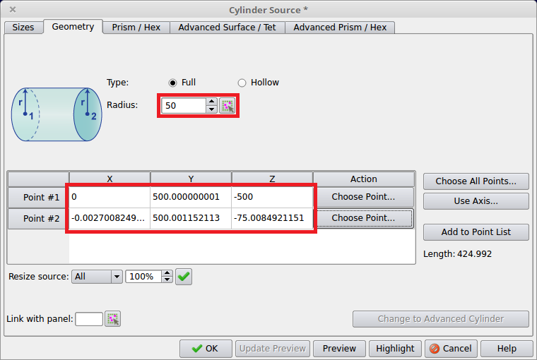
Setting up the Cylinder geometry.
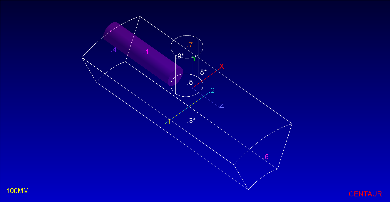
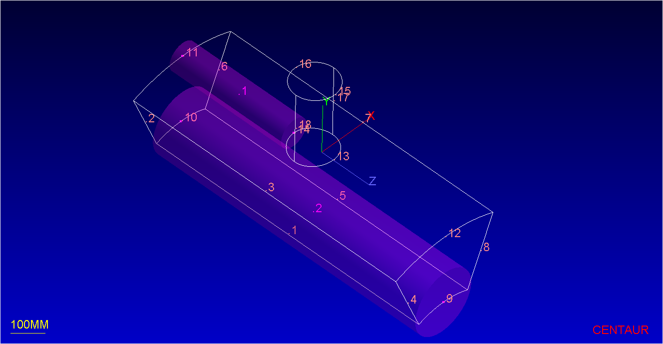
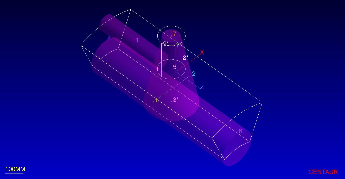
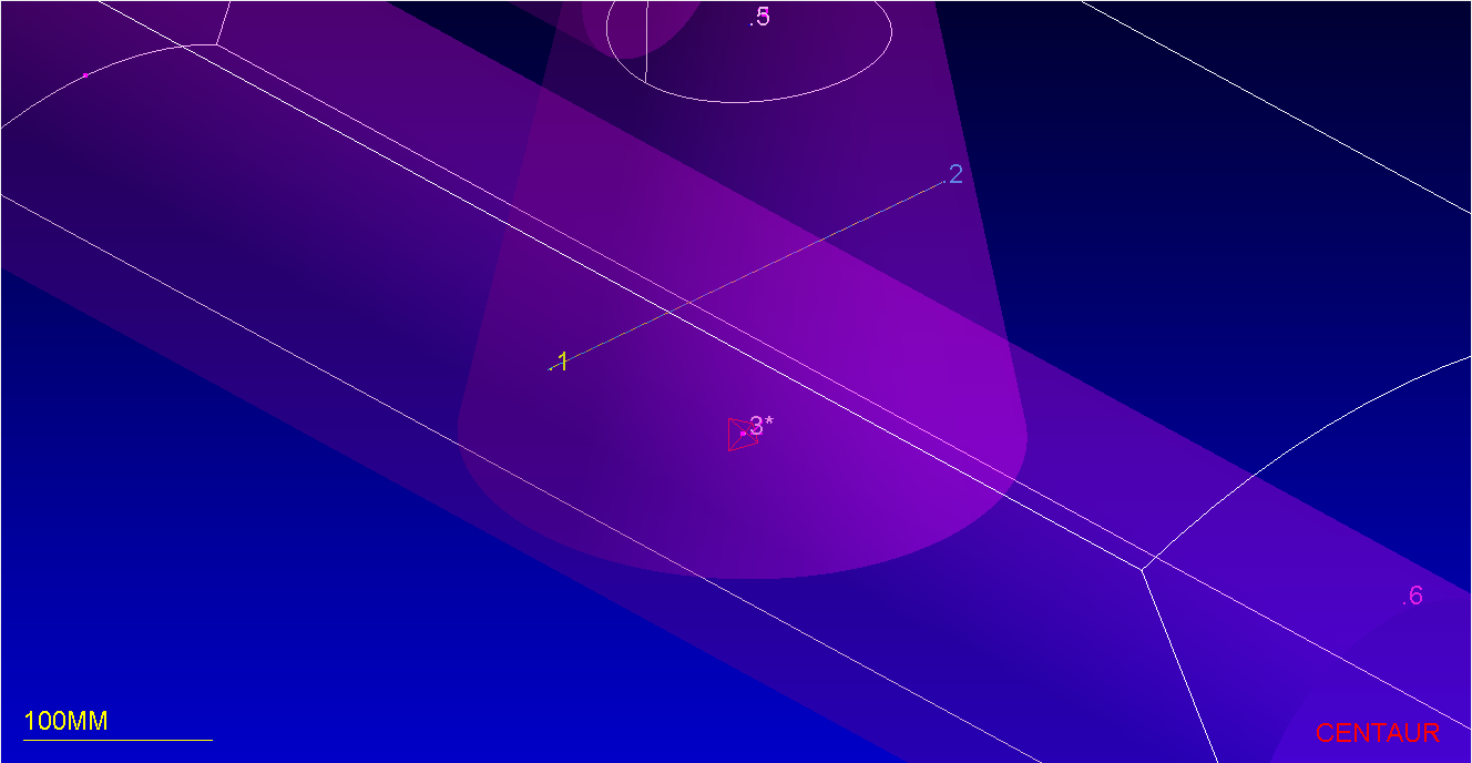
The sources are shown here with the geometric source shown by a pink cylinder and the CAD sources shown with asterisks next to the panel numbers (note that the View Mode has been switched back to Panel):
Note that when Point Selection window is open, it is also possible to interactively select points in the graphics window using the mouse. Simply click on the desired point location after the point selection window has been opened using the Choose Point button for each point in the Geometry tab. If a red dot appears under the mouse cursor, that means that the location of the panel/curve label or curve endpoint will be used precisely for the point location.
Step 3: Generate a Surface Mesh
Mesh generation for the final mesh cases proceeds as above using the Mesh Generator>Generate New Mesh… option and selecting Stop after Surface for the Stage and use tubes_src for the casename.
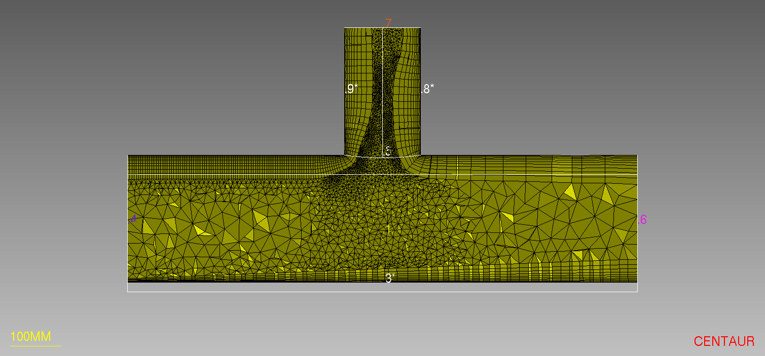
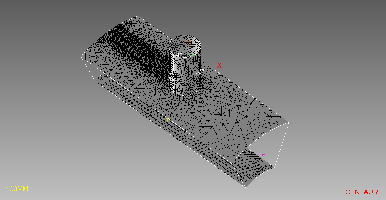
Automatically loading the resulting mesh file, tubes_src.fvs, into the program shows the effect of all 3 sources:
Step 4: Create a Prismatic Source
Next, a prismatic source will be applied to the hub region that allows the prismatic thickness to vary from the Inlet to the Outlet panel. To create a source with a variable size, a geometric source must be created. Make sure to switch from the Visualizer sidebar to the Setup sidebar display before setting up the new sources.
This source will go from the middle of curve 10 to the middle of curve 9, so these curves must be added to the Point List as in Step 2 above: select curves 10 and 9 and then use the L hotkey twice.
After the points are added to the list, create a cylindrical source named Hub 2 (Sizes Tab) using those two points and set a radius to 110 (Geometry Tab):
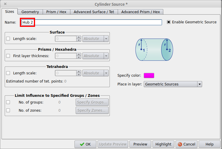
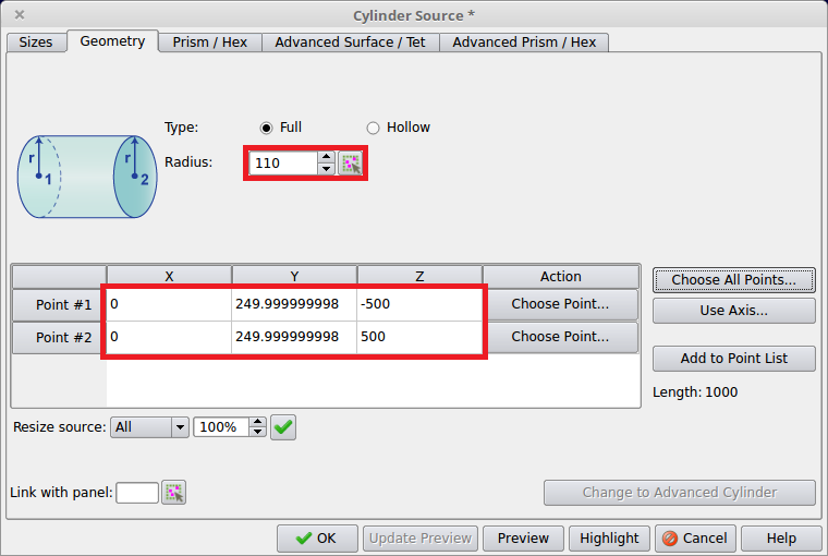
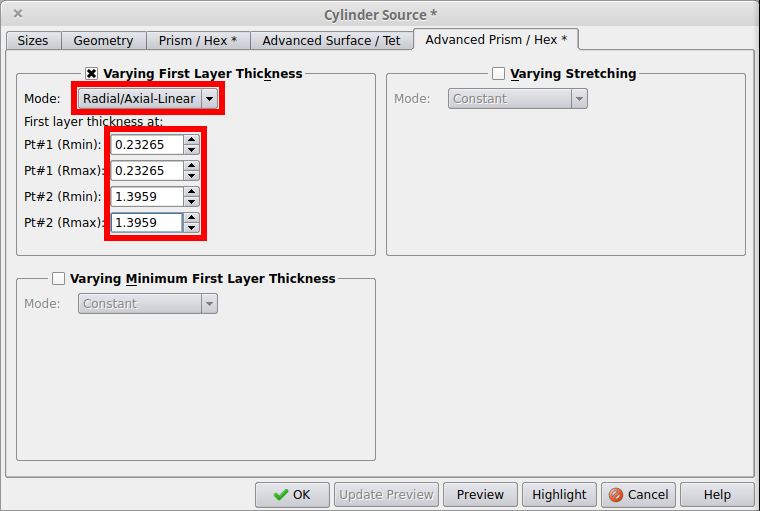
Since the size will vary from one end to the other, double check the locations of the two endpoints to prevent the size from varying in the wrong direction.Then use the Advanced Prism / Hex Tab to allow for the size to vary from one end of the source to other. Turn on Varying First Layer Thickness and switch the mode to Radial/Axial-Linear and specify the following sizes:
Pt#1 (Rmax): 0.23265
Pt#2 (Rmin): 1.3959
Pt#2 (Rmax): 1.3959
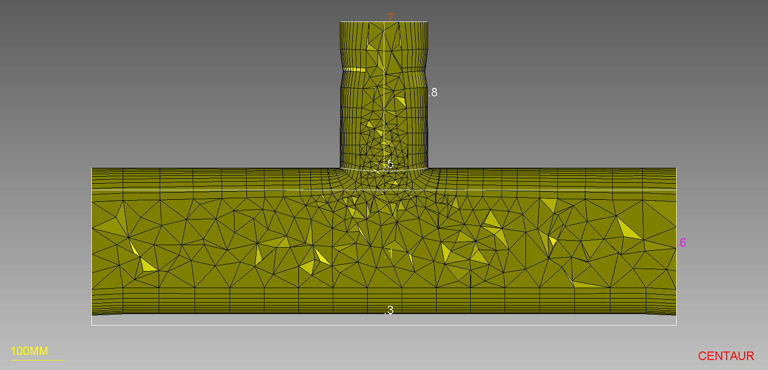
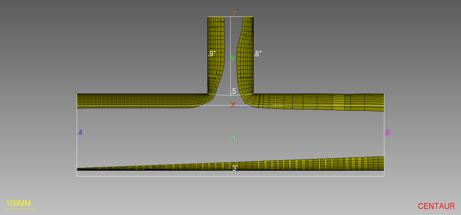
This will lead to the following configuration:
Step 5: Generate a Prismatic Mesh
Step 6: Create a Tetrahedral Source
Finally, a tetrahedral source will be added down the centerline of the tube inlet all the way to the center of the hub surface. A Relative type source that reduces the sizes of the tetrahedra in the region to 60% of their original size will be used. In general, the Relative type sources set the ratio between the local element size and the element size due to other factors (i.e. CAD Clustering, Curvature Clustering, Proximity Clustering). It is suggested to use them for fine-tuning of a generated/reference mesh.
As in Steps 2 and 4 above, the point list will be used to store the ends of the geometric source. This time panels 7 and 3 should be selected and added to the list with the L hotkey. Adding a panel to the point list will add the location where the label is drawn on the screen which is the middle of the panel’s underlying surface.
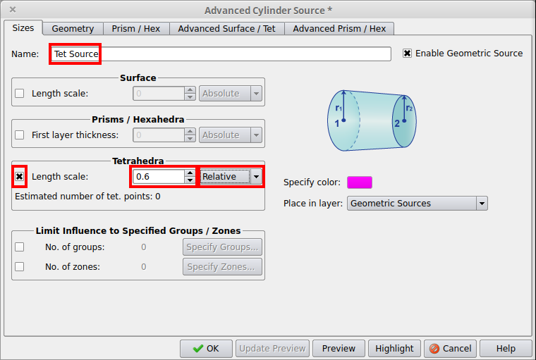
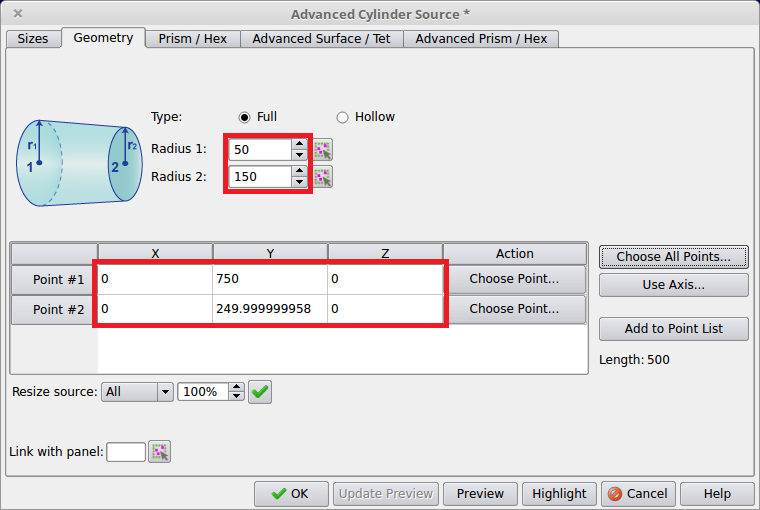
Then, an Advanced Cylinder source should be created with the name Tet Source, Radius 1=50, Radius 2=150, activated for Tetrahedra with a value of 0.6 and the type set to Relative.
Note that when Point Selection window is open, it is also possible to interactively select points in the graphics window using the mouse. Simply click on the desired point location after pressing the point selection window has been opened using the Choose Point button for each point in the Geometry tab. If a red dot appears under the mouse cursor, that means that the location of the panel/curve label or curve endpoint will be used precisely for the point location.
If the sources need to be changed, the Source Management window can be used. This window is opened using either the Source>Manage Sources… option or the ![]() toolbar button. This window allows for sources to be modified, created or highlighted allowing for easy control over cases with multiple sources. Through this window, the user can also select to “Show sizes” in order to inspect the requested source sizes before the mesh generation. The sizes of the source elements are then shown as wireframe tetrahedra.
toolbar button. This window allows for sources to be modified, created or highlighted allowing for easy control over cases with multiple sources. Through this window, the user can also select to “Show sizes” in order to inspect the requested source sizes before the mesh generation. The sizes of the source elements are then shown as wireframe tetrahedra.
Step 7: Generate a Hybrid Mesh