Mesh Quality
This tool allows for inspection and improvement of the mesh quality. Specifically, for inspecting the mesh quality the following tools are available:
- Quality metric distributions plots (histograms)
- Visualization of quality metrics via color plots
- Visualization of elements of poor quality
As far as quality improvement is concerned, tetrahedra can be adjusted after the mesh has been created to meet user-specified quality criteria (no need to regenerate the mesh).
A broad spectrum of quality metrics can be used to check the mesh quality. The available metrics are categorized per mesh part, as follows:
- Surface (Wall Faces)
- Boundary Layer (Prism / Hex)
- Element Transition (Interface)
- Tetrahedra
- 2D (Tri. / Quads)
Note: Customer-defined quality metrics can be included in the mesh quality tool per request.
When To Use:
Usually the quality of the hybrid grid is adequate for performing flow simulations since on-the-fly quality constraints are imposed during the mesh generation process. However, it is strongly recommended to check the mesh quality after each mesh generation stage finishes. For the surface and boundary layer mesh, the user can intervene locally (e.g. using sources) to correct the mesh. For tetrahedra, which are typically slower to generate, it is recommended to used the quality improvement tool. The tetrahedral portion of the mesh can be adjusted based on the user-specified quality goals.
How to Use:
This tool can been run through the MeshQuality menu options in the GUI as it will be described below. Tetrahedral mesh quality improvement can be alternatively run at the command prompt using the improvegrid command as follows:
improvegrid casename.hyb 3 casename.imp
Additional information on how to use this tool can be found in the following tutorials:
Workflow Example:
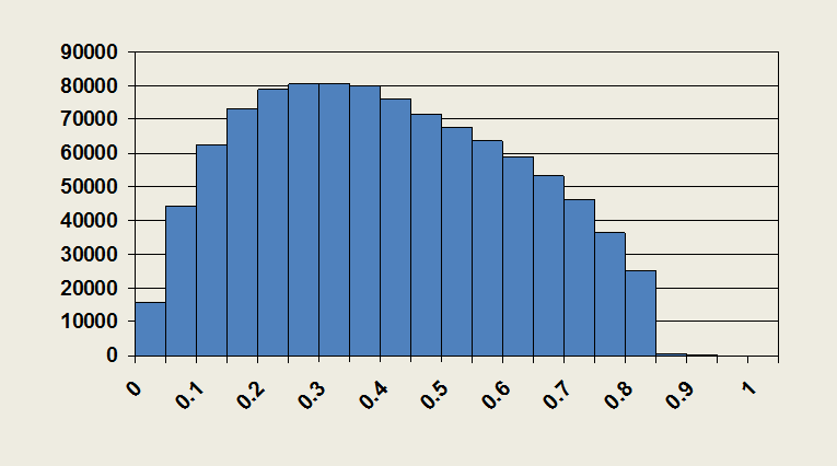
First, the quality metrics that will be studied need to be specified via the Choose Metrics… option. Next, the distributions of the selected quality metrics can be visualized via histograms. This can be done by clicking on the Histograms… option in the menu. Mesh quality statistics, namely the minimum, average and maximum values of the quality metric, are also displayed when visualizing the histograms.
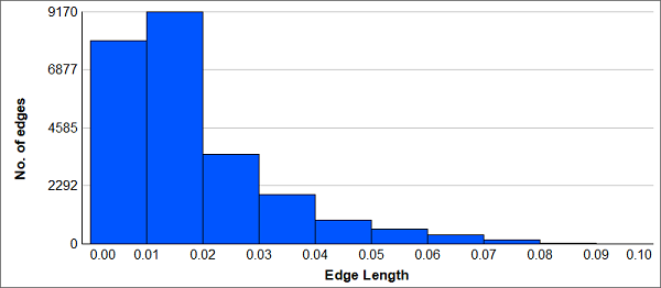
Edge Length Quality Metric Distribution
Additionally, surface and boundary layer quality metrics can be visualized via color plots by using the corresponding option in the MeshQuality menu. A special surface mesh file including the user-specified quality metrics is loaded in the Visualizer sidebar. For the boundary layer metrics, the “worst” value found in a prism/hex stack is extrapolated on the wall surface.
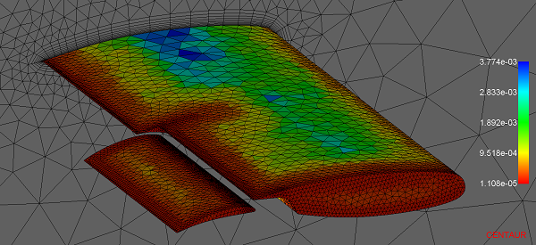
Surface Mesh (Wall Faces) Colored According to Face Area Quality Metric
The portion of the mesh that does not meet the quality goals set by the user can be inspected via the Bad Elements… option. Provided a mesh and user-specified threshold values that “filter” the poor quality elements, a special mesh file (.badelems) is loaded in the Visualizer sidebar which shows the locations of the elements identified as bad. The identified elements are listed per quality metric. If the mesh is about to be regenerated, visualizing the bad elements can be of help for the creation of local sources in the regions where the quality goals were not met.
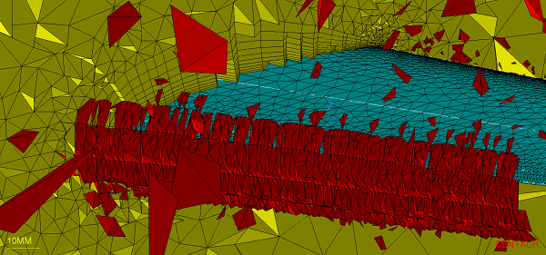
Identified Elements based on User-specified Quality Criteria (Sliver > 3)
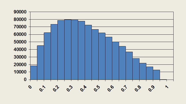
Finally, the tetrahedral mesh quality can be improved via the Tet. Quality Improvement… option. Provide the mesh to be improved, select the quality metrics that will be addressed and specify the target values according to the solver needs. The process can be run via the GUI or the setup can be saved into a file (.imp) and run in batch mode.
An example of the effect of the quality improvement tool on the tetrahedral mesh skewness can be seen in the following figures:
 |
 |
| Equivolume skewness BEFORE tet. mesh quality improvement |
Equivolume skewness AFTER tet. mesh quality improvement |