Create Block Wizard
The Create Block Wizard is a step by step tool used to create blocks that are used to produce high quality locally structured meshes. Blocks can be either attached to the geometry, connected to other blocks, or floating in the domain interior. The wizard can be started either directly via the Blocks/Hexahedra>Create Block… option or using the Create Connected Block Toolbar button: ![]()
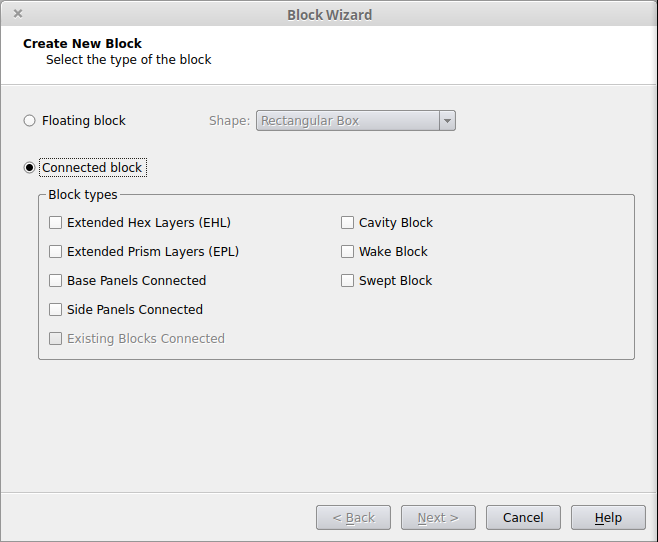
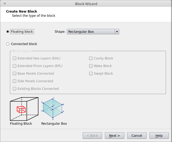
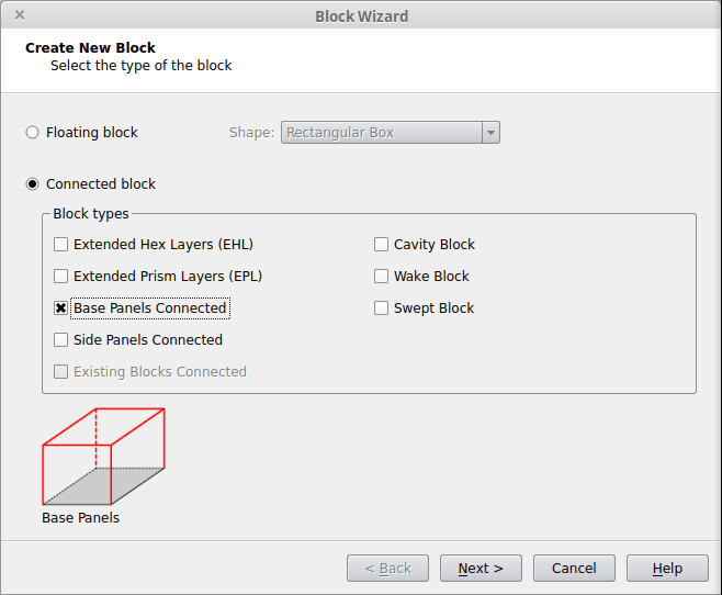
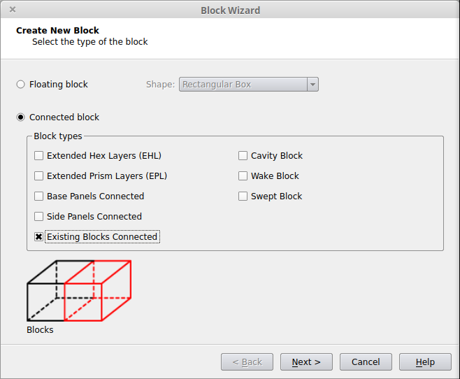
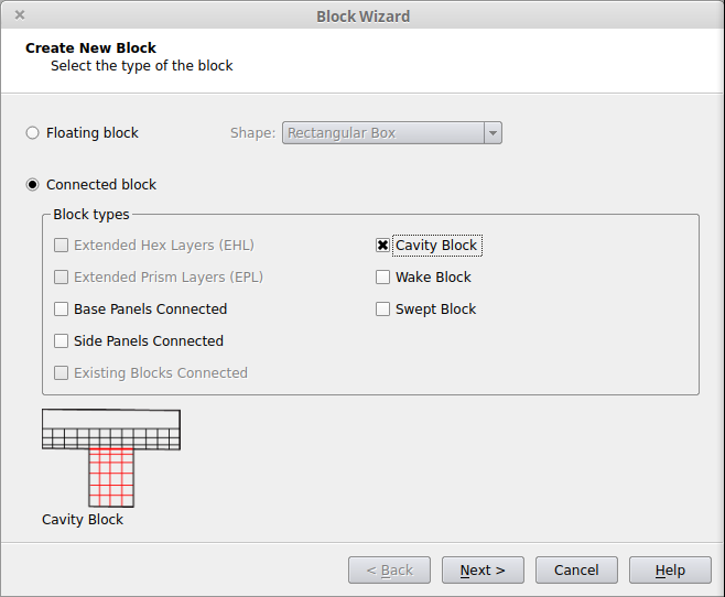
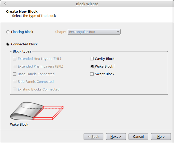
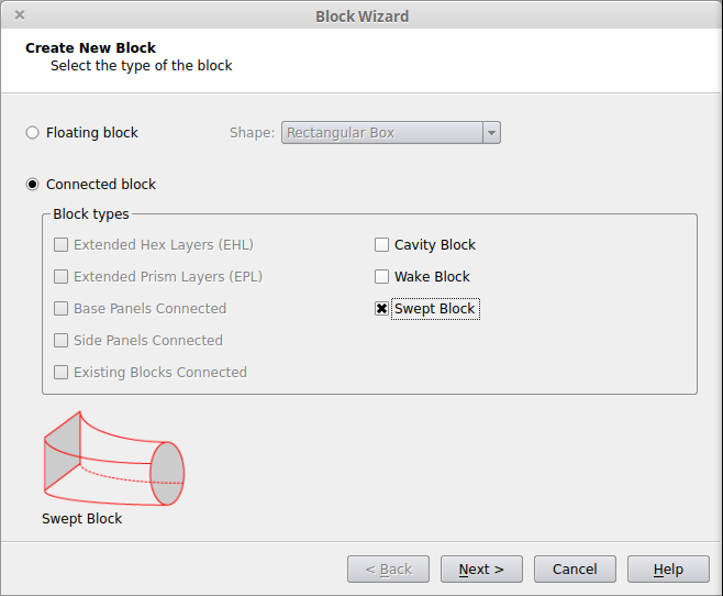
The first page of the wizard defines how the block will be connected to the existing case. Depending on which options are checked on the first page of the wizard, different pages of the wizard will be used. If multiple options are selected, the process will use pages from the various categories below as needed.
| Option | Usage |
|---|---|
| Floating |
|
|
Extended Hex Layers (EHL)
|
|
|
Extended Prism Layers (EPL)
|
|
|
Base Panels Connected
|
|
|
Side Panels Connected
|
|
|
Existing Blocks Connected
|
|
|
Cavity Block
|
|
|
Wake Block
|
|
| Swept Block |
|
Related Tutorials
- Basic Extended Hex Layers (EHL) Tutorial
- Advanced Extended Hex Layers (EHL) Tutorial
- Extended Prism Layers (EPL) Tutorial
- Free (Floating) Blocks with Side Panel and Hex Block Connections Tutorial
- All Hexahedra Tutorial
- All Hexahedra (Split Face) Tutorial
- Advanced All Hexahedra Tutorial
- Fill Gaps with Blocks (All Hexahedra) Tutorial
- Hexa Blocks for Pipes and Holes Tutorial
- Cavity Blocks Tutorial
- Special Cavity Blocks Tutorial
- Swept Blocks Tutorial
- Transition Blocks Tutorial
Floating Blocks
Extended Hex Layers (EHL)
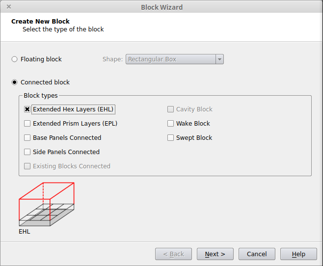
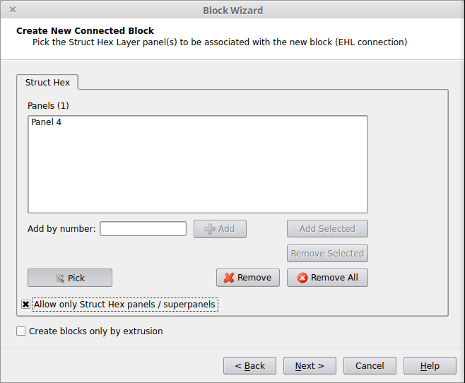
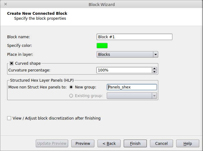
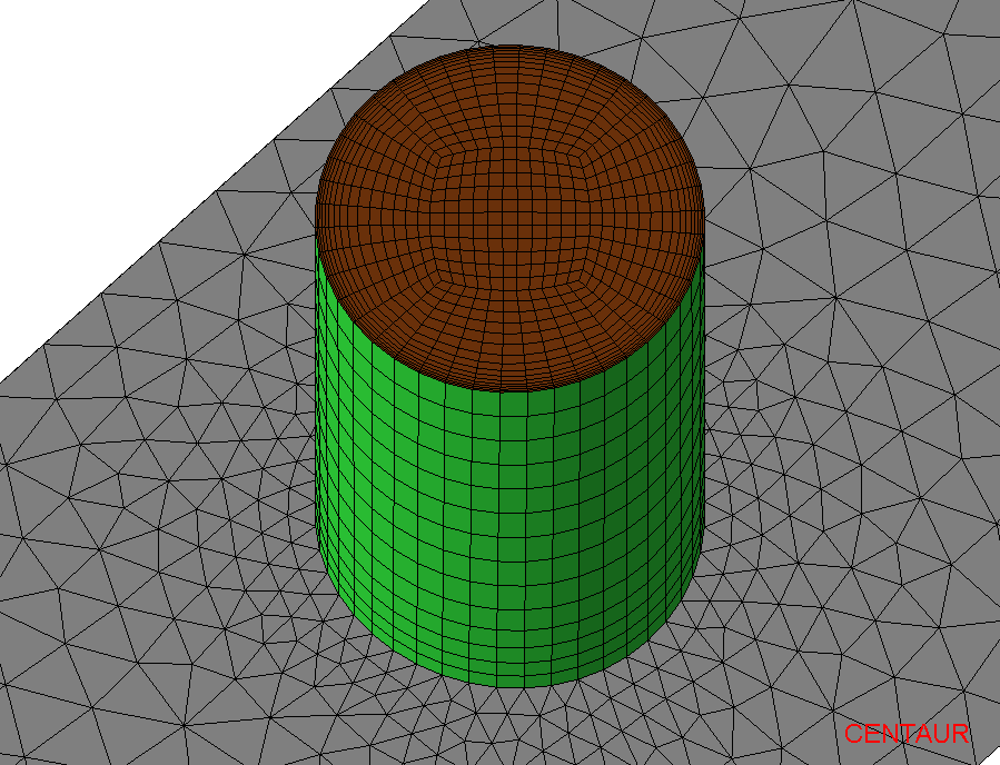
This option creates one or more Extended Hex Layers blocks. An Extended Hex Layers block is a structured hex block that is attached to the outer layer of a region of structured boundary layer hexahedra, grown from a Struct Hex panel or superpanel. This allows for the hexahedra to continue from the boundary layer mesh into the interior of the domain. Extended Hex Layers connections are only allowed to panels that are in groups with the Element Type set to Struct Hex. If the panels are not already in such groups, the groups will be modified or a new group will be created at the end of the process.
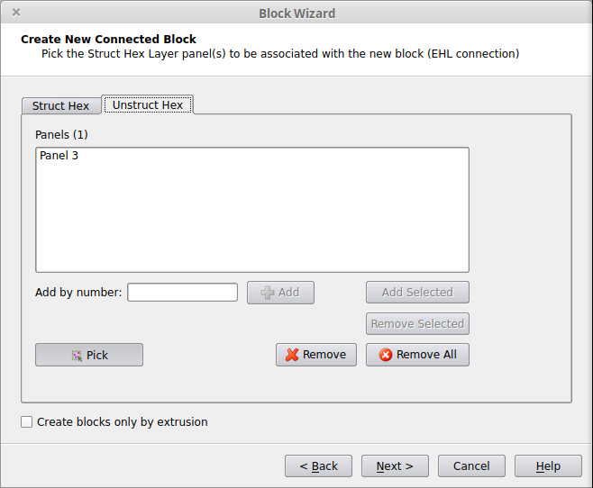
If the current case has any panels that are in Unstruct Hex groups, then there will be an additional tab, Unstruct Hex, that will allow for those Unstruct Hex Panels to be picked. Note that forming a EHL block from an Unstuct Hex Panel will result in a block containing semistructured hexahedra instead of structured hexahedra.
For Unstruct Hex, only 2-, 3-, or 4-sided panels or superpanels with no inner trimming loops will be able to be picked during this step.

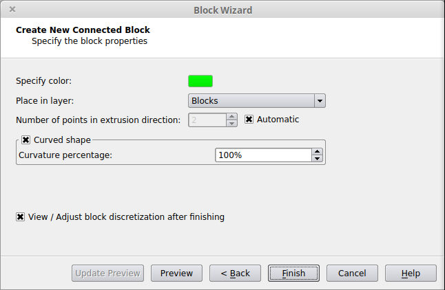
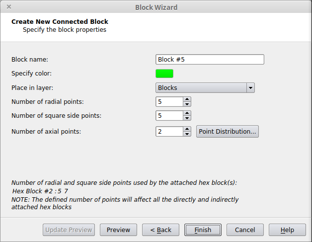
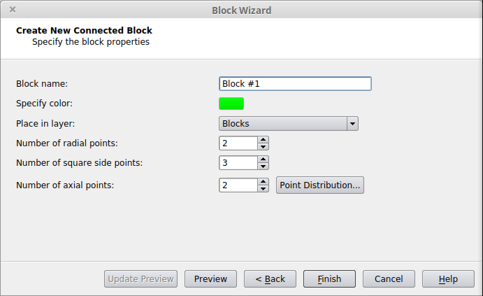
Define the Hex Block Properties:
Related Tutorials
Extended Prism Layers (EPL)
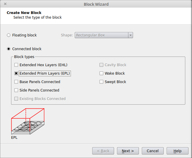
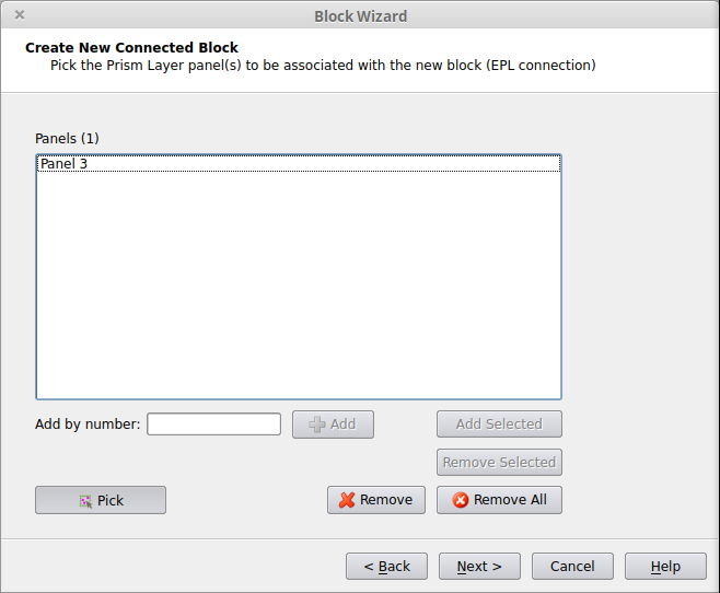
This option creates one or more Extended Prism Layers blocks. An Extended Prism Layers block is a semi-structured block of prisms that is attached to the outer layer of a region of boundary layer prisms, grown from a Prism panel or superpanel. This allows for the prisms to continue from the boundary layer mesh into the interior of the domain. Extended Prism Layers connections are only allowed to panels that are in groups with the Element Type set to Prisms. If the panels are not already in such groups, the groups will be modified or a new group will be created at the end of the process.
Define the Block Shape
Define the Block Properties:
Related Tutorials
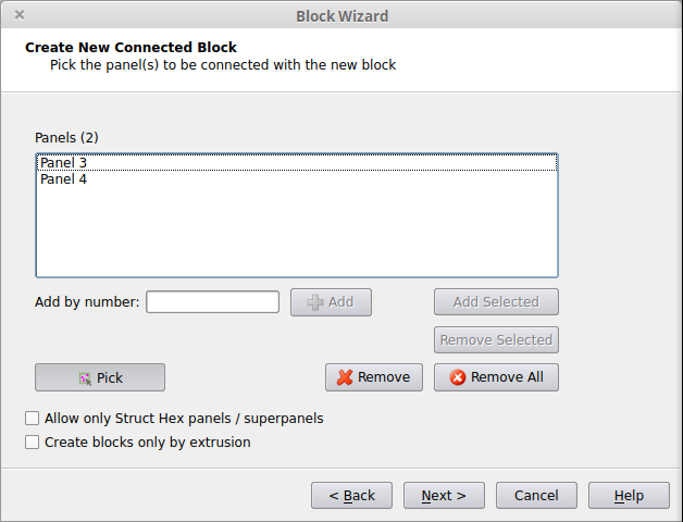
Base Panels
This option will connect the new block directly to any 4-sided panels or superpanels in the geometry. This allows for fully structured meshes to be created for entire domains or subdomains (simple regions of complicated geometries).
Define the Block Shape
Define the Hex Block Properties:
Related Tutorials
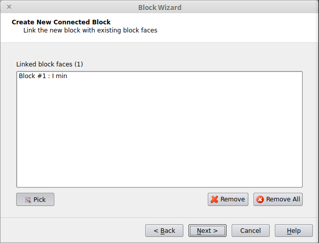
Existing Blocks
This option allows for a new hex block to be created that is directly linked to one or more existing hex blocks.
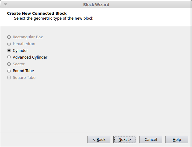
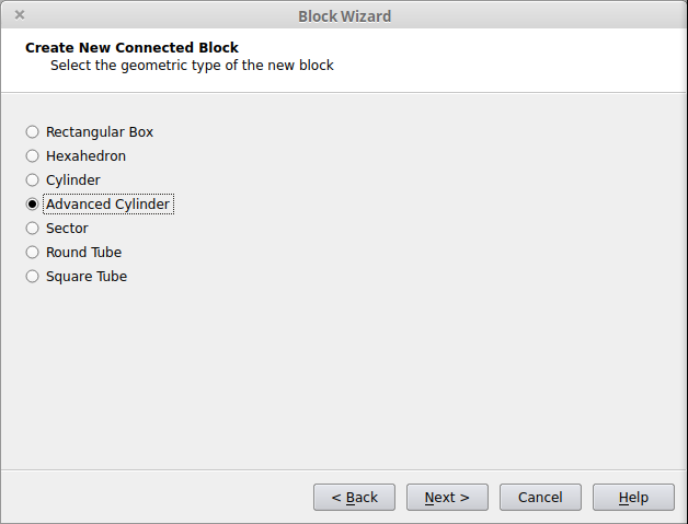
Select the Geometry Type of the New Block
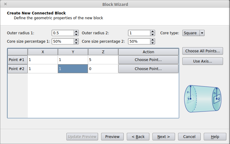
Define the Hex Block Properties
Related Tutorials
Side Panels
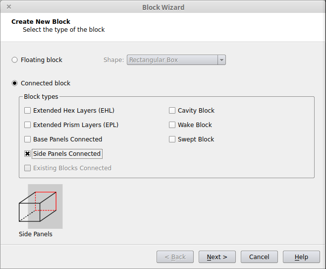
This option allows for the sides (or ends) of a hex block to connect to the CAD without the need for transitional elements between the block and the geometry. For the Side Panels option, connections are only allowed to panels in groups with the type Hybrid or Tetrahedra.
Select the Geometry Type of the New Block
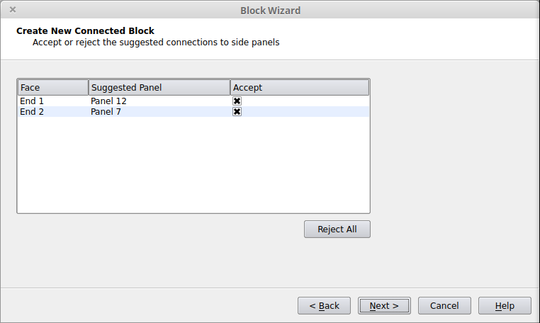
Review any suggested Side Panel connections.
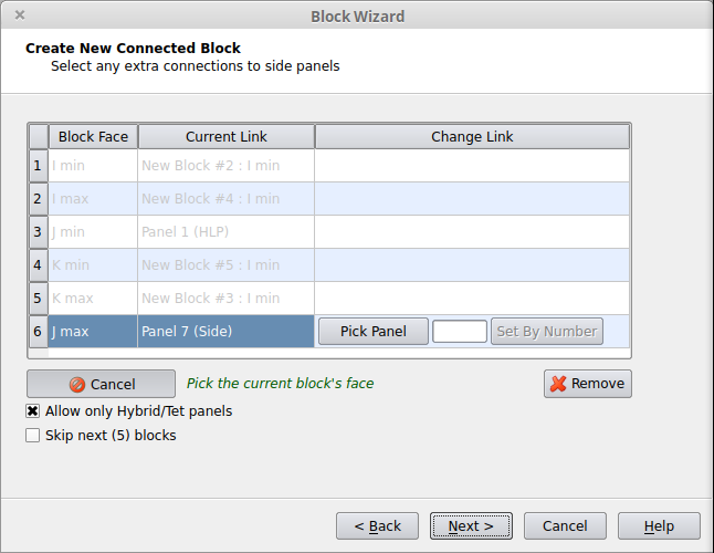
Link the Block to more side panels (optional)
Define the Hex Block Properties
Related Tutorials
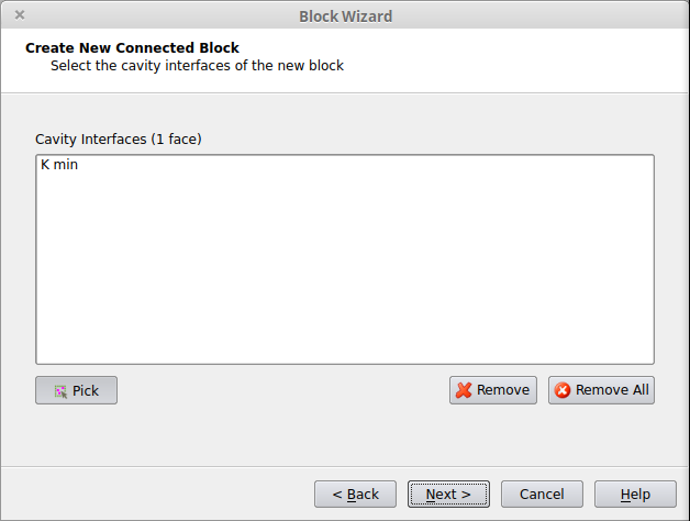
Cavity
Related Tutorials
Wake Blocks
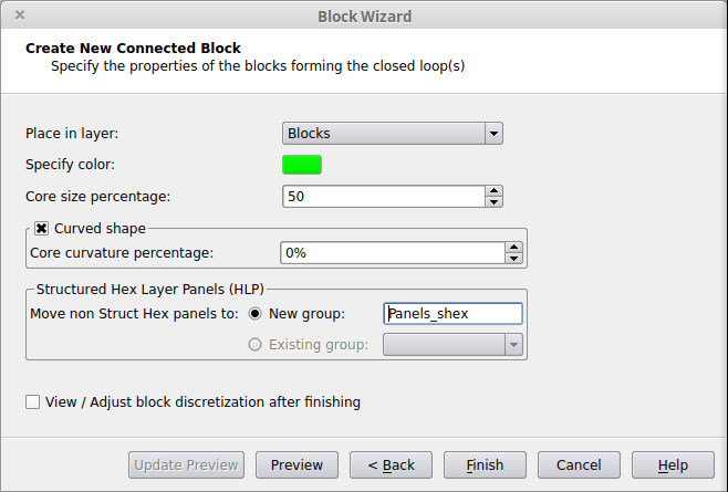
Swept Blocks
Tubes/Pipes Blocking
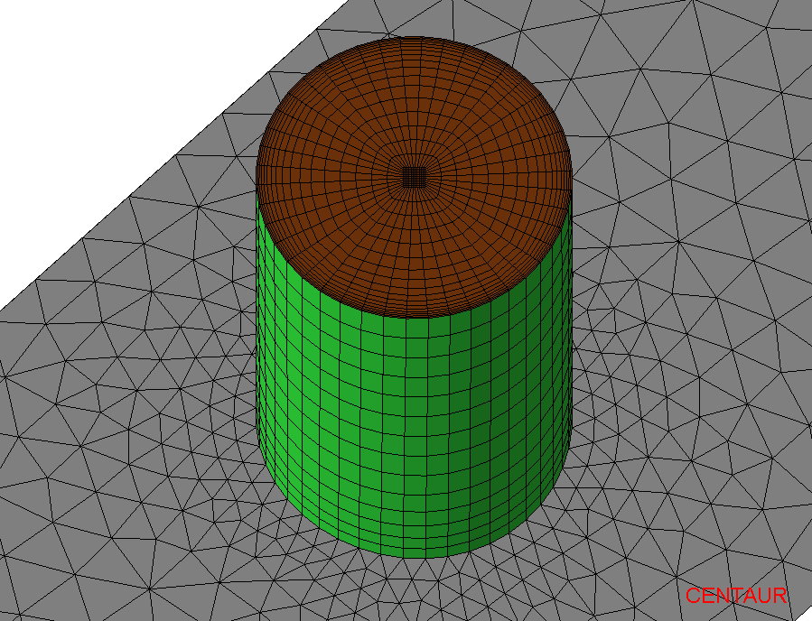
| Core size percentage=10% | Default Core size percentage=50% |
Core size percentage=80% |
|---|---|---|
 |
 |
 |
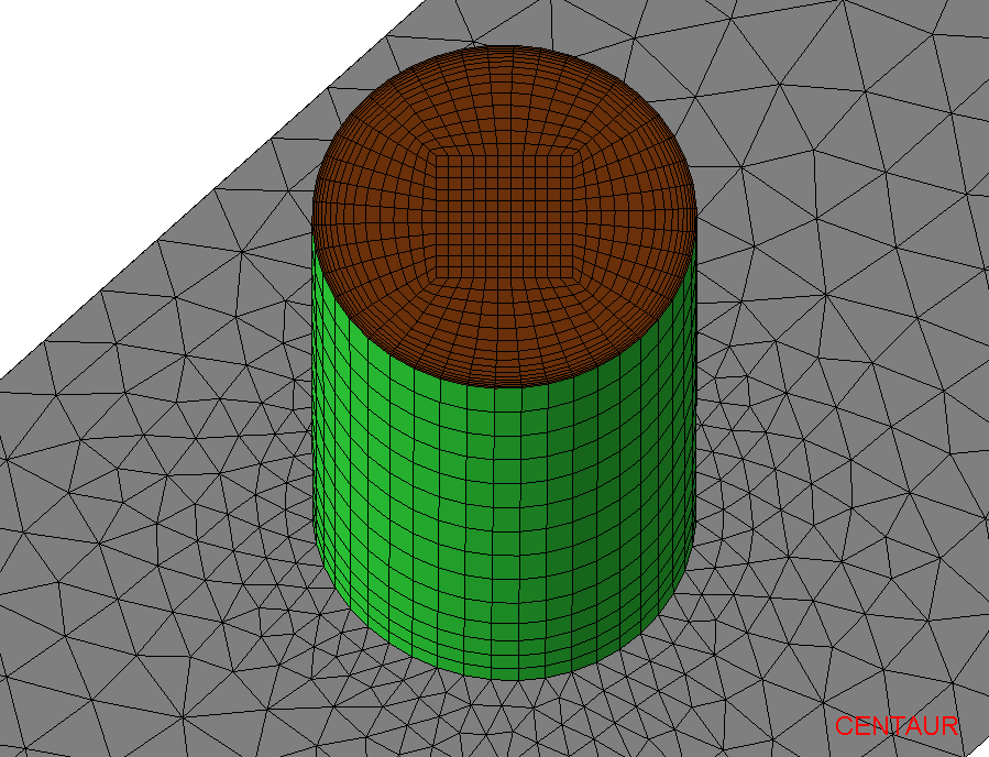
| Default Core curvature percentage 0% |
Core curvature percentage 40% |
Core curvature percentage 80% |
|---|---|---|
 |
 |
 |
Related Tutorials
Blocks with General Shape
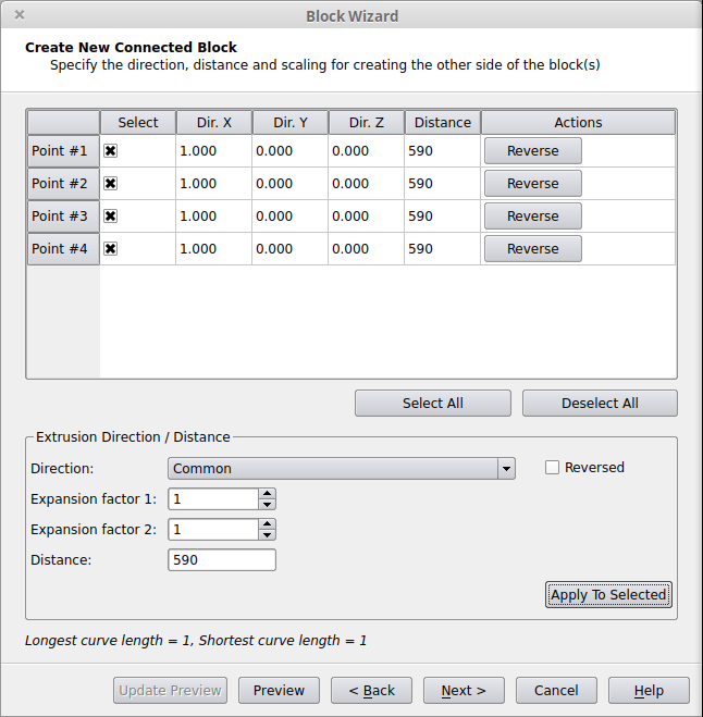
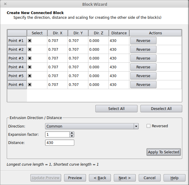
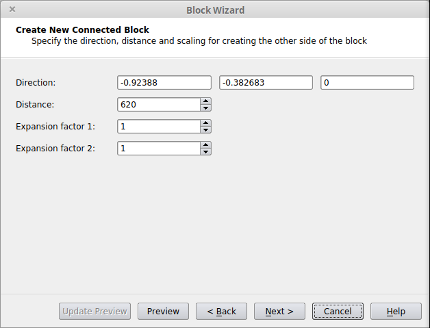
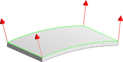
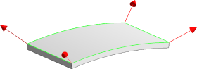
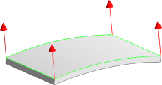
The shape of a block attached to the geometry (Extended Hex Layers block, Extended Prism Layers, or Base Panel block) is defined based on the extrusion direction and distance set for each corner point of the panel(s) from which the block grows.
The direction can be initialized based on the following options:
 |
 |
 |
| Individual (based on picked panels) |
Individual (based on picked/neighbor panels) |
Common |
Regardless of the option selected, each vector can be modified via adjusting the X, Y, Z direction and its length (extrusion distance).
An example of a general-shaped block attached to local panels on the upper surface of a wing is shown below: